Archive for November, 2012
ALP new vacuum pump
Posted by () in Open Notebook Science on November 9, 2012
Vacuum pump
Today, Damian and I setup the vacuum pump that we got from the surface sputter working. It wasn’t very smooth going but, in the end it worked. Here’s what we did.
Found a plug box that had a spot for a fuse—which turns out to be very important to the story—and an on on/off switch.
We then connected the wall outlet to the box, and then the box to the pump. We flipped the switch and nothing happened. This lead us to believe that the way we had it connected was wrong and that we needed to switch the polarity of the wires to the pump. So, I did and flipped the switch and guess what, nothing happened.
Next we decided to find another pump. We tried the solvent pump but it didn’t pump the tube down enough so we nixed that. Then I found a really old one in a drawer and decided to plug it in to see if it worked. Well, it may have worked before it decided to self destructed in a plume of smoke and a giant spark. The issue was that the plug was not polarized and as such, I put it into the wall socket incorrectly and thus blew it up—really just the power cable fried. See the below images.

As you can see, the wire connected to the pump incinerated off of it leaving a nasty burn mark on the bench.

After that light show, Damian realized that we may have blew the fuse in the box that we connected to the first pump so we checked it. Sure enough it was blown.
We got another fuse and I connected it again with the switched polarities since we still didn’t know which way was correct. This blew the fuse.
So, we got another fuse and I switched the polarity back to what we had it at initially. This time the pump worked. Turns out the first fuse we used was not rated at the current needed to supply the pump so it blew the first time we turned it on. When I switched the polarity the first time, no current was being supplied to the pump because the fuse was already dead.
After screwing the terminal box back onto the pump, Damian and I turned it on for a sustained amount of time after I overfilled it with oil. This caused the pump to spit and spew oil all over te place. Fun. Nonetheless, we cleaned the filter and got the oil to a proper fill line and I connected it to the tube to see if it would work. Sure enough, it worked swimmingly.
Hugh and I took a trip to the hardware store and bought some proper fittings for the tube since we determined last week that we needed to decrease the amount of resistance the air flow encountered in order to increase the flow rate to the desired 90L/min. This was a smart move since in the below image, you can see the flow rate reaching over 300L/min.

This is awesome!
Motor control
I also had the pleasure of working with Gio and Tyler as well. Today we destroyed one of my H-bridge Arduino shields and I think we definitively decided that the ATX power supply is not working. We burned out the shield by supplying it too much current/voltage when we were using it with a laboratory power supply. I’m not entirely sure why it blew but my suspicion is that the power supply swung the voltage over the rated amount for the board when we had the current limit high thus frying it. It died without an explosion, just a little pop.
The good news is that the big easy driver came in, the Arduino still functions and Tyler gets to learn how to convert an ATX power supply into a lab power supply. This was great work today!
ALP vacuum notes
Posted by () in Open Notebook Science on November 5, 2012
Today Damian and I got to play around with the vacuum. We were brainstorming how to increase the amount of air flow through the inhaler using the in-vitro lung and I must admit I was quite stumped when we were discussing it. Never having worked with vacuum before, I lacked the basic knowledge of how to think about it. But, thanks to the work of Danielle and her post about flow through an orifice, I think I understand what is going. Also thanks go to Damian for speaking his mind and indicating that what we were wanting to do may not be necessary. Good job! Below are my notes on what Danielle and Damian taught me.
Danielle wrote in her post that the volumetric flow rate can be written as
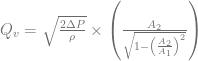
where 


where again 

			Tube
		=========================	       ________
Vacuum	       |			|Inlet _______/        |
	    ___|			|_____/	               |
       [--] ___		      A2	 _____	       Inhaler |
	       |			|A1   \_______	       |
	       |			|	      \________|
		=========================
The inlet is what is connected to the inhaler on the right side of the tube and the left most side of the tube is where we pull the vacuum. Now, we need the air flow through the inhaler to be at least 90L/min. But, the inlet serves as an obstruction, a resistance if you will. I will get back to the idea of resistance in a moment. As we know, Bernoulli’s equation will tell us what the fluid flow through the inlet will be if we know the following: pressure inside the tube, the pressure outside the tube, and the velocity of air in the tube.
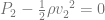
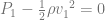
Now, if we look at Bernoulli’s equation in the tube (2) and it in the inlet (1) we obtain two sets of equations.


which can be written as
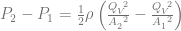
and thus setting them equal to each other gives


We can equate these together because of conservation of mass which just means that the air that flows through the inlet isn’t going to disappear in the tube because well, it can’t. Now, if we replace the velocities with a volumetric velocity, i.e. 
and then
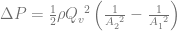
giving

This is readily solved for


Going through this hoopla teaches us a couple things. One important thing is that the volumetric flow rate—the quantity we need to increase—depends on the pressure difference between the tube and the orifice in a nonlinear fashion. It also tells us that the only way to increase the flow rate is to either increase the pressure differential or, make 
Inspecting the above equation also taught me an analog to vacuum and current. If I have a wire and I put current through it, the electrons will happily move along the wire with no problem. But, if I add a resistor to the wire, the rate at which the electrons move down the wire is changed. The same thing happens in our vacuum tube when air flow meets a change in diameter. The fluid flow hits a resistance and thus slows the bulk fluid motion down if the diameter is decreased.
This is good. And yes, you were right Damian. This of course means that you (Damian) are going to need to figure out a way to pull a better vacuum on the tube.
ALP Friday 2012-11-2
Posted by () in Open Notebook Science on November 4, 2012
On Friday Danielle and I worked on the vacuum tube a bit. We replaced the regulator for a ball valve and noticed that the flow through the Aerolizer increased from the previously stated 45L/min to about 75L/min. While this is an improvement, we need to get it up to 90L/min.
Once we can get it to 90L/min, we will need to ensure that it maintains that level of airflow for at least 4 seconds. That may require us to add length to the tube which should be fine.
Finally, we need to get some more fittings for the tube. I’ll attempt to go to the hardware store to find some.
