Archive for category Particle-Surface Interactions
Friday
Posted by () in Open Notebook Science, Particle-Surface Interactions on March 23, 2012
Sputter coater
Damian and I tried even more things. Including removing and cleaning all connections to the chamber. Nothing worked. We even globed on a bunch of vacuum grease every where to see if there were inadvertent leaks. Again, nothing worked.
Accelerometer power supply
Sarah and I completed the power supply modifications today. This is good news as we can now start looking at the accelerometer for the pendulum
Non ferrous stirrer.
Tommy needed a stirrer for magnetic nanoparticles. So, I ripped apart a hand drill that functioned off of a 6V battery pack. Unfortunately, the battery pack was dead and the charger didn’t work. So, I swapped out the battery pack for a 6V wall wart with not a lot of current. This is fine as the stirring doesn’t need to be fast. By removing the battery pack, the ability to change the speed went away. I’m guessing that there is some way to reinstate this. In the mean time, sorry Hugh for ripping apart your old hand drill. I will fix it when it is no longer needed. The stir bar is a glass pipet that was cleaved and the paddle is a microscope slide that is epoxied to the pipet. No metal!
Thursday
Posted by () in Open Notebook Science, Particle-Surface Interactions on March 22, 2012
Sputter coater
The sputter coater has 2 valves that control the exhaust (for when you want the chamber to return to atmospheric pressure) and the other for filling the chamber with the gas of your choice. In order to determine if the release valve is the culprit for our leak, I did the following things.
- Removed the release valve and re-Teflon taped the filter and hose connected to it.
- Completely bypassed the release valve and rigged together a manual release valve.
Neither of these things worked. Rather than try to fuss with the valves, I am going to remove all connections to the chamber and try to find a way to test pressure inline with the vacuum pump. Perhaps the actual chamber is the problem.
- Plug all connections to the chamber and test.
If the chamber isn’t the problem, then it may be the pressure gauge. That, I can’t fix and will be an absolute bear if we need to replace it since the machine is out of production.
Roughness
Continuing with my other interests in roughness, I obtained the original Hamaker publication which talks about the aptly “Hamaker coefficient” that I have been reading about. I plan to rederive the coefficient for two spherical bodies as it should be interesting.
I have been able to read Hamaker’s original article
Hamaker HC (1937) The London-van der Waals attraction between spherical particles. Physica 4:1058–1072. http://dx.doi.org/10.1016/S0031-8914(37)80203-7.
and I have worked through his calculations. I am getting a sign error for some reason and will have to investigate that later. In the very least, it feels good to do some math and flex my integrating muscles. I’ll post my calculations in a later post.
Wednesday
Posted by () in Open Notebook Science, Particle-Surface Interactions on March 21, 2012
Sputter Coater
The sputter coater is down due to the device’s inability to pump the sample chamber to the required pressures to sputter. Damian and I have tried the following things to try and fix it.
- Cleaned the pump.
- Changed the hose.
Unfortunately, neither of those fixed the problem. I just now switched out the pump with a different one and the same problem is occurring. My next steps are:
- Change out the hose material.
- Re-teflon tape the other hose connectors that are connected to valves etc.
Changing the hose material did nothing for the pumping. Actually, it made it worse so it is most definitely not the hose, nor is it the pump. This leaves the following connections that need to be checked:
- Gas inlet hose.
- Pressure gauge.
- Gas mixing valves.
Drat…a lack of Teflon tape is preventing me from looking at the rest of the valves.
Roughness
Another project that is related to fixing the sputter coater is to investigate roughness. I feel like I am spinning my wheels on this one a good amount as the paper I am reviewing:
- Rabinovich YI, Adler JJ, Ata A, Singh RK, Moudgil BM (2000) Adhesion between nanoscale rough surfaces: I. role of asperity geometry. Journal of Colloid and Interface Science 232:10–16. PMID:11071726. http://dx.doi.org/10.1006/jcis.2000.7167.
is not easy to follow as there seem to be missing steps with the RMS roughness calculations. Especially since I feel like equation 4 is coming out of left field with its coefficients. Of course, this is probably because I don’t know the field well enough…I am currently investigating other references but I am finding it difficult to find articles.
Pendulum debugging
Posted by () in Open Notebook Science, Particle-Surface Interactions on December 9, 2011
Pendulum holder
So, the next step for the pendulum was to try and hold it in one spot and let it go in a reproducible way. To do this, Sarah and I decided to use some 1/4″ Loc-Line coolant tubing. This stuff is great and will become a staple in my tool arsenal from now on. The concept is not new and was repurposed from an Instructables post that I came across a while ago. We purchased ours from McMaster-Carr part number 10095K11. The point of using the Loc-Line tubing is to release the pendulum in a reproducible manner. We want to know what forces the pendulum will hit the target when it is let go at a specified angle and using the tubing is an attempt to reduce error when letting go of the pendulum.
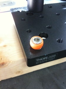
The first thing to do was to modify one of the adapters that came with the package from McMaster-Carr to allow it to be mounted to the Thorlabs breadboard. To do this, I sawed the adapter shown in Figure 1 in half.
 |
| Figure 1: Loc-Line Adapter. In order to attach the Loc-Line coolant system to the breadboard, I had to saw one of the adapters in half. I used the one that a 1/4-20 screw could fit through. |
Figure 1 shows one of the two adapters that came in the package. I sawed it in half and stuck a 1/4-20 through it and mounted it on the breadboard, Figure 2.
Once the Loc-Line Breadboard Adapter is positioned where one wants it, it’s just a matter of sticking the tubing on the adapter. This is no small feat of strength but, it can be done. Figure 3 shows the Loc-Line Pendulum Holder in action. It basically just holds the pendulum up from the bottom. When you want to let it go, you just move the tubing out of the way. This configuration was found to be the most stable.
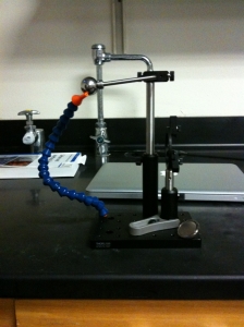 |
| Figure 3: Loc-Line Adapter. The Loc-Line pendulum holder in all it’s glory. It works quite well. To release the pendulum, one just moves the Loc-Line system out of the way. |
Magnet holder
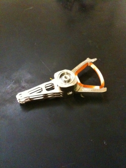
The magnet holder was another complicated issue that needed addressing. When the pendulum came to the bottom of its swing, it would impact the magnet. The impact of the pendulum on the magnet is not whimpy and would cause the magnet to shatter. This was a problem as I’d like to prevent the device from destroying itself. To prevent this from occurring, a suitable spacer was needed. This came in the form of a hard drive compression gasket seen in Figure 4. Ahh computer junk, the source of so many DIY devices.
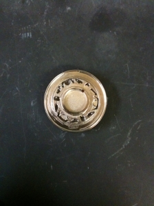 |
| Figure 4: HD gasket.. The wonky looking thing is a hard drive compression gasket used to keep the HD from spinning out of its box. There is a magnet epoxied to the other side. |
Figure 5 shows the pendulum spacer, magnet, and the pendulum together. The spacer prevents the pendulum from coming in contact with the magnet thus preserving it. I’m not sure what the material is of the HD gasket. I think it’s titanium as it is nonferrous and tougher than aluminum.
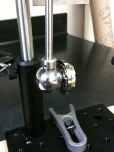 |
| Figure 5: Magnet spacer. The pendulum ball fits nicely in the center hole of the HD gasket. The pendulum does not impact the magnet directly thus preventing it from shattering. |
Sample holder
As much fun as it is to get to build something, this bugger is becoming irritating due to the fact that we have been having to epoxy things together. While epoxy is good for somethings, I dislike the stuff and would much rather use mechanical fasteners when ever I have the chance. Glue is good for wood but, not so much so for metal. Que sera…
The point of this device is to be able to measure quantities of chemicals coming off of different chemical substrates. To do this, we have to collect the chemicals being flung off of the substrate. We decided on using scintillation vials as the way to collect materials being de-adhered from a substrate due to the impact of the pendulum. Hmm, I like that sentence. In order to mount the vial in the pendulum, the optics holder was used, see Figure 6.
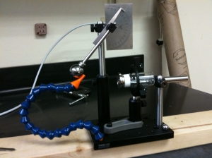 |
| Figure 6: 4th iteration. Fourth version of the pendulum. The scintillation vial is being held by the optics holder. It is prevented from moving backwards with the optical posts due to an impact. |
The amount of force being imparted to the scintillation vial is enough to cause the holder’s grip on the vial to slip. This is why a set of optical posts were used to prevent the vial from moving backwards, seen as the metal posts opposite to the pendulum weight. The cap of the vial is attached to the magnet holder which creates a mechanical connection to the vial. Thus, when the pendulum hits the magnet, its impact force will be imparted to the objects of interest attached to the cap.
I’ll show a movie of the pendulum in action once the epoxy on the cap dries. Sarah and I already tried it before the epoxy had time to cure and it just destroyed the epoxy on the cap. So, rather than have to re-epoxy it again, I’m not going to try it now. I’ve done a couple of dry run whacks with the pendulum and a blank cap and so far, it looks great.
I’ll admit that I’m irritated with myself about how long it took to debug this thing. Although, I’m super excited that the problems that did arise were solved easily through communication. Be it with open notebook science, talking with the students in the lab, or Hugh, the pendulum progressed into a solid device in a relatively short period of time. The only two possible kinks left are force calibration and the epoxied cap that holds the substrates.
Debugging the particle-surface pendulum
Posted by () in Open Notebook Science, Particle-Surface Interactions on December 2, 2011
The bearing I purchased from McMaster-Carr had way too much slack in it. This caused the weight to acquire a tilt to it when it was at rest, see Figure 1.
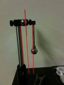 |
| Figure 2: Ball bearing slack. The above image shows the slack in the ball bearing that was purchased from McMaster-Carr. The red lines are there to help guide the viewer. |
To alleviate this, I opened up an old hard drive lying around the lab and salvaged the voice-coil hard drive head-reader, see Figure 2.
Of course, the new bearing doesn’t fit into the holder I got for the original bearing. This isn’t a problem as I found a nut that Sarah epoxied onto the bearing. The epoxy takes 3 days to cure so we will know if it will work on Monday. I did use some 5 min epoxy on it to show that it will work. 5 min epoxy is not good enough for the parts unfortunately. The retaining ring is a bit more difficult to get into place but, that will just have to be the way it is.
The next issue is to try and get the pendulum to be held in one place and release without issues. One thing I noticed when both Sarah and I were attempting to release the weight, we both gave it a little upward kick without realizing it. This is an issue that needs to be resolved. In Figure 3, I have setup a simple mockup behind what we would like to do. It doesn’t work that great but it does remove me or another user from giving the weight an upward motion before release.
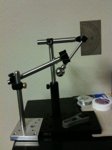 |
| Figure 3: Pendulum holder. A simple (and bad) way for holding the pendulum in place. There has to be a better way. |
I have Sarah right now investigating different materials that we could use in order to make a better holder. She is right now looking at different materials we can use that would fit better on the base. Things such as flexible coolant hoses, third hands, etc.
Particle-Surface Pendulum
Posted by () in Open Notebook Science, Particle-Surface Interactions on November 29, 2011
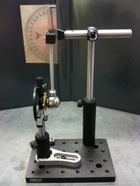
Here is an actual picture of the pendulum and a movie of it in action.
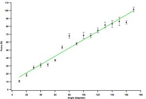
Here is some calibration data taken by a new undergraduate to the lab, Sarah D. Labianca.
Here is a movie of it in action.
Particle-Surface Interactions Pendulum
Posted by () in Open Notebook Science, Particle-Surface Interactions on November 28, 2011
My new boss, Hugh Smyth, has given me the green light to do open notebook science on some of the projects I’m working on in the lab. The project I’ll discuss below is especially cool since it is simple and relatively straight forward to accomplish. Plus, the fact that Hugh is excited about open notebook science makes it all the more fun.
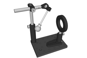
What I designed is a very simple pendulum that has the capability to whack the heck out of something. Figure 1 is a SketchUp image of the pendulum showing the basic design.
It works surprisingly well and I’m happy about its design. There are a few issues with it that I will discuss when I post real images of the build. Till then, here is a parts list for, what I’m calling the “Pendulum 5000”.
Parts List
Thorlabs
- MB4 – 4″ x 6″ Aluminum Breadboard.
- BE1 – Pedestal Base Adapter.
- CF125 – Small Clamping Fork.
- PH2 – 2″ Post Holder.
- TR2E – 2″ Optical Post.
- LH1 – Adjustable Lens Mount.
- PH4 – 4″ Post Holder.
- TR4 – 4″ Optical Post.
- TR6 – 6″ Optical Post.
- RA90 – Right Angle Post Clamp.
- LMR15 – Lens Mount for Ø15 mm Optics.
- ER2 – 2″ Cage Assembly Rod.
- ER3 – 3″ Cage Assembly Rod.
- MSCB1 – Tapped Mini-Series Construction Cube.
- MSA25 – Thread Adapter 1/4″-20 to 4-40
McMaster-Carr
- 92311A535 – 1/4″-20 Set Screws.
- 7804K143 – Flanged Double Shielded Ball Bearing.
- 92185A535 – SS 1/4″-20 Socket head cap screw 3/8″.
- 8517A58 – Stainless Steel Protractor.
Precision Balls
As a final note, getting Figure 1 to display properly was a heck of a feat due to my lack of HTML skills. So, I’m going to post the code for it below. The reason why I didn’t use the built-in WordPress figure + caption gui is that it wouldn’t allow me to bold or italicize words in the caption. So, I had to build a table to stick the figure in. Even posting the below code was a pain since the symbols < and > are rendered as HTML tags and need to be escaped with their ASCII equivalents.
<div id="image" style="width: 330; margin:0 auto; background: lightgray;">
 <table class="image">
  <tbody>
   <tr>
    <td align="center"><a href="http://image"><img class="size-medium wp-image-20" title="" src="http://image" alt="" width="300" height="200" /></a></td>
   </tr>
   <tr>
    <td class="caption" align="left"><strong>Figure 1:</strong> <em>Title</em>. Caption</td>
   </tr>
  </tbody>
 </table>
</div>


