Archive for December, 2011
Posted by () in Literature review, Open Notebook Science on December 21, 2011
Disclaimer
The following review is my own interpretation of the linked-to article. Please do not use my review as a complete reference for the article as I will most likely skip important information that you feel is relevant. If I do miss something, please feel free to comment about it in the comments section below. Please read the article before reading my review and remember, this is my notebook, which means these are my notes on the article and they will more-than-likely hold no relevance to you or your research.
Paper
Review
In this paper, the authors did both experiments and calculations on biofilms. They used an interesting device called a Biofilm Airlift Suspension device which, is used to study wastewater treatment.
- The authors confirmed my suspicion that the structures of biofilms are highly dependent on the flow of the medium that they are in. This paper does not go into that analysis rather they reference a paper that did.
- Gjaltema A, Tijhuis L, van Loosdrecht MCM & Heijnen JJ (1995) Detachment of biomass from suspended nongrowing spherical biofilms in airlift reactors. Biotechnol. Bioeng. 46: 258–269.
- The authors stipulate that the dominant factor governing biofilm morphology is a ratio of the detachment rate to the the biofilm surface loading rate.
- While I agree with this statement, I do not believe it is the root reason why biofilms obtain a certain morphology. I still think is is dependent on flow rates of the environment the biofilm is in. So, I think Navier-Stokes has to come into play at some point.
- They reference an article that states that shear rates govern the thickness of biofilms as do lower surface loading rates.
- Kwok WK, Picioreanu C, Ong SL, van Loosdrecht MCM, Ng WJ & Heijnen JJ (1998) Influence of biomass production and detach- ment forces on biofilm structures in a biofilm airlift suspension reactor. Biotechnol. Bioeng. 58: 400–407.
- They define the biofilm density as the amount of biomass per volume excluding the pores in the biofilm. They state that this is a measure for the number of cells in the biofilm.
- They reference another paper that investigated biofilm density. This paper showed that biofilm density increased when the substrate used selected for slower growing bacteria. This paper also showed that fast growing bacteria in a low shear rate and a high loading rate led to more porous biofilms.
- Villaseñor JC, van Loosdrecht MCM, Picioreanu C & Heijnen JJ (2000) Influence of different substrates on the formation of biofilms in a biofilm airlift suspension reactor. Water Sci. Techn. 41(4–5): 323–330.
- They reference another attempt at mathematically modeling biofilms in one dimension.
- Wanner O & Gujer W (1986) A multispecies biofilm model. Biotechnol. Bioeng. 28: 314–328.
- They also discuss other references where more advanced studies were done modeling biofilms.
- They are apparently using the model defined by Picioreanu. This model incorporates several parameters:
- Convection
- Diffusion
- Reaction
- Biofilm growth
- Detachment
- The authors note that at the time of the writing, proper measurements of the gel properties of biofilms still have not been accomplished. This is interesting and now gives me a better search term “biofilm properties”. They do give several references.
- The author’s final thought is to obtain experimental data in the following areas in order to improve computational reliability.
- EPS formation kinetics and stoichiometry.
- Biofilm mechanical strength.
- Kinetics of production and decay of quorum sensing signals.
- Biomass spreading in the biofilm.
- Movement of biofilm filaments.
- Movement of the biofilm itself.
I think the take-home from this paper is that they were able to model biofilms. This was definitely a review paper even though it didn’t state that it was. The important things I learned were:
- Fast flow rates give a denser less porous biofilm.
- Low flow rates give a more porous biofilm.
Also, I completely agree with the author’s desire to get more experimental data in their closing remarks. Actually, everything they suggested are questions that I have about biofilms and I need to search for every term above.
Literature review
Posted by () in Literature review, Open Notebook Science on December 20, 2011
Disclaimer
The following review is my own interpretation of the linked-to article. Please do not use my review as a complete reference for the article as I will most likely skip important information that you feel is relevant. If I do miss something, please feel free to comment about it in the comments section below. Please read the article before reading my review and remember, this is my notebook, which means these are my notes on the article and they will more-than-likely hold no relevance to you or your research.
Paper
Review
I decided to ask the question; what is a biofilm? Usually, I would start with a review on the subject to try and answer this question and this is exactly what I decided to do. Again, as usual, I “picked” the first review article I found from a Google Scholar Search. Too bad the article isn’t OA.
- The authors state that biofilm formations appear in fossil records dating back to 3.25 billion years ago.
- Figure 1 is pretty spectacular and is well commented.
- They make a compelling argument stating that; making biofilms is an ancient and integral part of prokaryotes.
- In the early evolution of Earth, there were extreme and fluctuating conditions such as UV, pH, and temperature changes. Having a biofilm to live in created a homeostasis were the bacteria could live and learn how to communicate. This is an interesting argument and they reference a paper for it.
- They also mention that creating biofilms could help sequester nutrients, they reference a paper for this statement as well.
- They define the following terminology: planktonic cells are those that are freely swimming in their environment while sessile ones are in a biofilm.
- They make a note of different ways in which bacteria will form biofilms and note that the structural similarities are possibly due to “convergent survival strategies”. Some of the convergent survival strategies include: streamers, periphyton, and stromatolite (defined in the paper).
- I have to disagree here as I cannot believe that a group of bacteria are actively creating structures in different environments. I can, however, attribute fluid flow aiding in structural similarities between the shapes of biofilms that form in say fast flowing environments as opposed to calm quiescent environments.
- They claim that “The proclivity of bacteria to adhere to surfaces and form biofilms in so many environments is undoubtedly related to the selective advantage that surface association offers.”
- I think they mean that bacteria have learned how to create biofilms because they are evolutionarily advantageous.
- They note that people have done studies where they attempt to knock out genes that show biofilm creation. In those studies, they found that knocking out the genes just retarded biofilm growth and thus it must be a fundamental and redundant gene in the bacteria….Very cool!
- Yes! They reference an article that did biofilm modeling.
- van Loosdrecht, M. C., Heijnen, J. J., Eberl, H., Kreft, J. & Picioreanu, C. Mathematical modelling of biofilm structures. Antonie Van Leeuwenhoek. 81, 245–256 (2002).
- Biofilms will release their colony in a few different means:
- Swarming dispersal.
- Clumping dispersal.
- Surface dispersal.
- They state that biofilms can be thought of as hydrogels.
- They state that there are (were in 2004) 3 proposed mechanisms to explain why biofilms are resistant to antibiotics.
- Barrier properties of the slime matrix.
- The physiological state of the biofilm. There are layers in the biofilm that have dormant cells and thus antibiotics end up being trapped there with not affect on the cells.
- Subpopulations of resistant cells.
- The authors state that Parsek and Singh (cited) proposed four criteria for defining a biofilm infection in a human.
- The pathogenic bacteria are surface associated or adherent to a substratum.
- Bacterial clusters, encased in a matrix of bacterial or host constituents.
- The infection is localized.
- The infection is resistant to antibiotic therapy.
- Bacteria will modify their phenotypes for biofilms.
So, the second half of the paper talked about biofilms on implants and cystic fibrosis. There was a ton of stuff in this section that I didn’t quite grasp so I’ll have to revisit it in the future. Overall, this was a good review of what makes biofilms, where they form, and some characteristics of them once they are created.
Pendulum debugging
Posted by () in Open Notebook Science, Particle-Surface Interactions on December 9, 2011
Pendulum holder
So, the next step for the pendulum was to try and hold it in one spot and let it go in a reproducible way. To do this, Sarah and I decided to use some 1/4″ Loc-Line coolant tubing. This stuff is great and will become a staple in my tool arsenal from now on. The concept is not new and was repurposed from an Instructables post that I came across a while ago. We purchased ours from McMaster-Carr part number 10095K11. The point of using the Loc-Line tubing is to release the pendulum in a reproducible manner. We want to know what forces the pendulum will hit the target when it is let go at a specified angle and using the tubing is an attempt to reduce error when letting go of the pendulum.
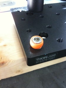
The first thing to do was to modify one of the adapters that came with the package from McMaster-Carr to allow it to be mounted to the Thorlabs breadboard. To do this, I sawed the adapter shown in Figure 1 in half.
 |
| Figure 1: Loc-Line Adapter. In order to attach the Loc-Line coolant system to the breadboard, I had to saw one of the adapters in half. I used the one that a 1/4-20 screw could fit through. |
Figure 1 shows one of the two adapters that came in the package. I sawed it in half and stuck a 1/4-20 through it and mounted it on the breadboard, Figure 2.
Once the Loc-Line Breadboard Adapter is positioned where one wants it, it’s just a matter of sticking the tubing on the adapter. This is no small feat of strength but, it can be done. Figure 3 shows the Loc-Line Pendulum Holder in action. It basically just holds the pendulum up from the bottom. When you want to let it go, you just move the tubing out of the way. This configuration was found to be the most stable.
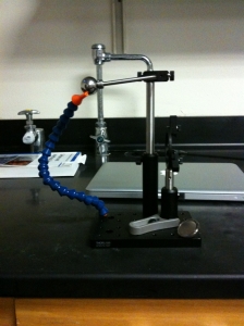 |
| Figure 3: Loc-Line Adapter. The Loc-Line pendulum holder in all it’s glory. It works quite well. To release the pendulum, one just moves the Loc-Line system out of the way. |
Magnet holder
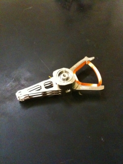
The magnet holder was another complicated issue that needed addressing. When the pendulum came to the bottom of its swing, it would impact the magnet. The impact of the pendulum on the magnet is not whimpy and would cause the magnet to shatter. This was a problem as I’d like to prevent the device from destroying itself. To prevent this from occurring, a suitable spacer was needed. This came in the form of a hard drive compression gasket seen in Figure 4. Ahh computer junk, the source of so many DIY devices.
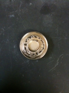 |
| Figure 4: HD gasket.. The wonky looking thing is a hard drive compression gasket used to keep the HD from spinning out of its box. There is a magnet epoxied to the other side. |
Figure 5 shows the pendulum spacer, magnet, and the pendulum together. The spacer prevents the pendulum from coming in contact with the magnet thus preserving it. I’m not sure what the material is of the HD gasket. I think it’s titanium as it is nonferrous and tougher than aluminum.
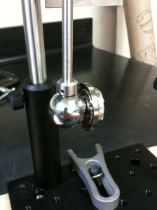 |
| Figure 5: Magnet spacer. The pendulum ball fits nicely in the center hole of the HD gasket. The pendulum does not impact the magnet directly thus preventing it from shattering. |
Sample holder
As much fun as it is to get to build something, this bugger is becoming irritating due to the fact that we have been having to epoxy things together. While epoxy is good for somethings, I dislike the stuff and would much rather use mechanical fasteners when ever I have the chance. Glue is good for wood but, not so much so for metal. Que sera…
The point of this device is to be able to measure quantities of chemicals coming off of different chemical substrates. To do this, we have to collect the chemicals being flung off of the substrate. We decided on using scintillation vials as the way to collect materials being de-adhered from a substrate due to the impact of the pendulum. Hmm, I like that sentence. In order to mount the vial in the pendulum, the optics holder was used, see Figure 6.
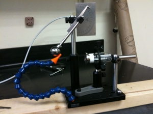 |
| Figure 6: 4th iteration. Fourth version of the pendulum. The scintillation vial is being held by the optics holder. It is prevented from moving backwards with the optical posts due to an impact. |
The amount of force being imparted to the scintillation vial is enough to cause the holder’s grip on the vial to slip. This is why a set of optical posts were used to prevent the vial from moving backwards, seen as the metal posts opposite to the pendulum weight. The cap of the vial is attached to the magnet holder which creates a mechanical connection to the vial. Thus, when the pendulum hits the magnet, its impact force will be imparted to the objects of interest attached to the cap.
I’ll show a movie of the pendulum in action once the epoxy on the cap dries. Sarah and I already tried it before the epoxy had time to cure and it just destroyed the epoxy on the cap. So, rather than have to re-epoxy it again, I’m not going to try it now. I’ve done a couple of dry run whacks with the pendulum and a blank cap and so far, it looks great.
I’ll admit that I’m irritated with myself about how long it took to debug this thing. Although, I’m super excited that the problems that did arise were solved easily through communication. Be it with open notebook science, talking with the students in the lab, or Hugh, the pendulum progressed into a solid device in a relatively short period of time. The only two possible kinks left are force calibration and the epoxied cap that holds the substrates.
Debugging the pendulum
Posted by () in Open Notebook Science on December 5, 2011
Still working on debugging the pendulum. Thanks to Hugh for figuring this little quirk out. The bearing that I was using previously was not up to cutting the mustard so, I culled one from a hard drive. The hard drive bearing worked great but, it didn’t fit properly in the Thorlabs holder. Hugh came in this morning and started playing around with the items and figured out that the new bearing I was using could be put in the right angle optical post holder with no problem. Unfortunately, doing so would cause a redesign that wasn’t the quickest thing to do. It did, however, fix a lot of issues and so, it won in the end because I’d rather have something working that can take data than redesigning it to make it keep original aspects. In life, business, and the lab, never get emotionally attached to a design because it’s either what your customer wants, or what makes you get the data that will win.
So, Sarah and I removed epoxy and re-epoxied things back together to incorporate this design shift. See Figure 1 for the new look.
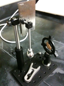 |
| Figure 1: Pendulum V3.0. This is the third design of the pendulum. It fixes some issues about stability with the bearing. |
It is much more compact and the most important thing, works nicely. The other issue with the pendulum was that the protractor was wonky. Meaning that it did not display angles correctly because of poor mounting. In order to mount the protractor read head properly, Sarah came up with the idea of using a grommet. I had a couple extra grommets lying around at home and brought one in. Thankfully it was a 1/4″ ID grommet that accepted the 6mm shaft properly. We decided to epoxy the grommet into place to prevent any movement of the read head from causing problems with measurements. See Figure 2.
So far, this is robust. The next step is to figure out the whole magnet thing and a better method for placing the pendulum at some height and letting it go. I think better magnets and the coolant hose idea will work.
Debugging the particle-surface pendulum
Posted by () in Open Notebook Science, Particle-Surface Interactions on December 2, 2011
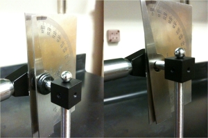
The bearing I purchased from McMaster-Carr had way too much slack in it. This caused the weight to acquire a tilt to it when it was at rest, see Figure 1.
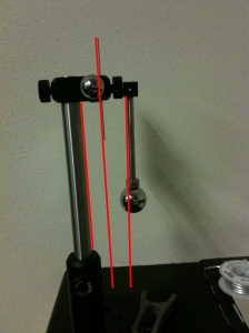 |
| Figure 2: Ball bearing slack. The above image shows the slack in the ball bearing that was purchased from McMaster-Carr. The red lines are there to help guide the viewer. |
To alleviate this, I opened up an old hard drive lying around the lab and salvaged the voice-coil hard drive head-reader, see Figure 2.
Of course, the new bearing doesn’t fit into the holder I got for the original bearing. This isn’t a problem as I found a nut that Sarah epoxied onto the bearing. The epoxy takes 3 days to cure so we will know if it will work on Monday. I did use some 5 min epoxy on it to show that it will work. 5 min epoxy is not good enough for the parts unfortunately. The retaining ring is a bit more difficult to get into place but, that will just have to be the way it is.
The next issue is to try and get the pendulum to be held in one place and release without issues. One thing I noticed when both Sarah and I were attempting to release the weight, we both gave it a little upward kick without realizing it. This is an issue that needs to be resolved. In Figure 3, I have setup a simple mockup behind what we would like to do. It doesn’t work that great but it does remove me or another user from giving the weight an upward motion before release.
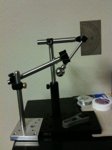 |
| Figure 3: Pendulum holder. A simple (and bad) way for holding the pendulum in place. There has to be a better way. |
I have Sarah right now investigating different materials that we could use in order to make a better holder. She is right now looking at different materials we can use that would fit better on the base. Things such as flexible coolant hoses, third hands, etc.

